Instructions
EazyRizer BIG BLUE Assembly & Instruction Sheets
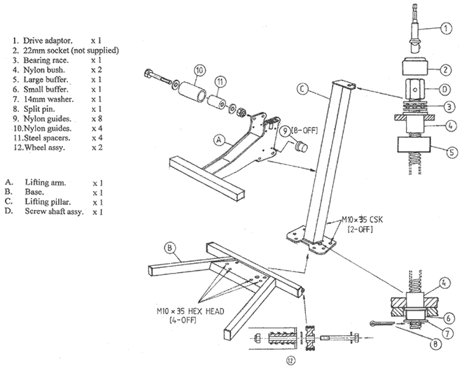
- Remove all packaging and check contents, now take the lifting pillar FIG C and after removing the screw-shaft assembly assemble it with base FIG B using the six M10 x 35 bolts and tighten them to 40 ft Ib.
- Turn upside down and fit the two wheel assemblies as shown in the diagram FIG 12 tightening the bolts until resistance is felt then back off a quater of a turn until the wheel is free to turn
- With the lift in the normal position take the lifting arm FIG A and remove the two outer guide bolts and fittings, now using a small amount of grease (supplied) fit the 8 nylon guides FIG 9 into their respective holes from the inside.
- Place the lifting arm onto the pillar and re-fit the two outer guides tightening all four bolts to 40 Ib ft and check that the lifting arm is free to move up and down the lift.
- Take the screw-shaft assembly and after greasing the bearing FIG 3 re-fit it to the lift as shown in the diagram, be sure to locate the large rubber buffer FIG 5 before screwing it through the bronze lifting nut in the arm FIG A.
- Continue screwing the shaft until it travels through the base plate and fit the nylon bush, small rubber buffer and 14mm washer as shown FIG's 4/6/7 and finally the split pin FIG 8.
- Assembly is now complete, lubricate the entire length of the shaft with the grease and with your power drill run the machine up & down several times. The lift is now ready to use.

